Blasting off

The spaceship’s body was to be approximately the size of an extra-large chicken egg or a Kinder Surprise chocolate egg! (We contemplated using lost ‘chocolate’ casting, but decided it would be better to just eat the chocolate.) On a serious note, we also rejected casting a plastic toy egg or carving a wax model by hand. Raising the egg from a sheet of silver was another option, but achieving the necessary accuracy would have been difficult and budget was a consideration.
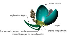
Therefore, we decided to use CAD. First, I modelled the basic shape using Rail Revolve, trimming the bottom of the egg to leave a flat bottom. Next, I drew three arcs on the lower surface and used them to first define and then split the ship’s lower engine compartment from the upper cabin section. At this point, since the egg was just a simple shell with no thickness, I had to bulk it up. For simplicity, I used CAD to split the upper cabin portion into three equal pieces, deleted two of them, and then used the single remaining piece for the next steps. I offset the original surface and drew the construction curves needed to create new connecting surfaces.

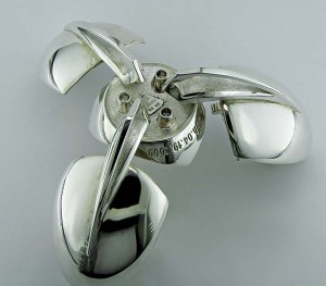
After joining these surfaces, I had a cabin section with 2-mm thick walls, heavy enough to be cast, but not too massive. In the top-down viewport, I used ‘rotate/copy’ to duplicate this piece to create the two remaining cabin sections. One of the cabin segments had the words ‘FUTURE PERFECT’ incised on the inside. Using the same offset surface method, I thickened the lower engine compartment section. Next, I added three exhaust ports to the bottom of this section and we inset CDA 04.19.2009 into the outside of the engine compartment.
The next step was to model one leg strut. Using the client’s original sketch as the impetus, I modelled a graceful leg with an open section and sleek curved surfaces to maintain an aerodynamic appearance. I added registration keys to the leg and cabin wall to permit accurate alignment in the final assembly steps. I replicated the finished leg twice and oriented one to the centre of each of the three cabin sections. I modelled hinge knuckles to attach to the lower ship section and used ‘Boolean subtraction’ to create corresponding sockets in the legs, with holes cut out for the hinge pin. Each leg and its attached cabin section were designed to pivot open from the lower engine compartment. The two angles on the bottom of the legs were chosen specifically so the ship would sit solidly on three legs in both the closed and fully open positions. Doing this in CAD enabled me to ensure the orientation and alignment would be as accurate as possible.


